
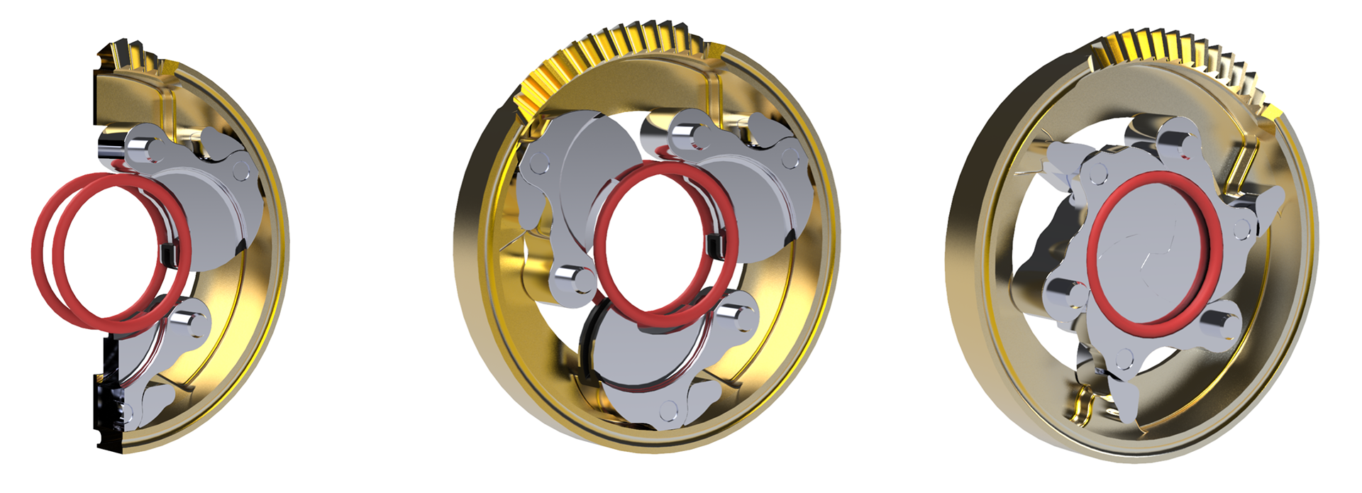
The 3-piece O-ring groove created by the valve petals in the closed position as a solution to survive high-cycle fatigue & wear
The Dilating Disk™ Valve employs a valve mechanism unlike any other design currently used for process control. Unlike the plug and seat combination of the globe valve, or the disc and seat configuration of a butterfly valve, the Dilating Disk™ Valve has 3 precisely machined, interlocking petals that are capable of ANSI Class IV, Class V, or Class VI bubble-tight shutoff, depending upon the application.
Challenge
The 3 petals that function as the throttling mechanism in the Dilating Disk™ Valve are essentially high-strength, robust metal blades that pivot about a hinge pin, into (or away from) the central opening of the valve, similar to the motion of scissors. The petals are driven by a rugged and efficient ring gear, which enables the Dilating Disk™ Valve to operate with minimal torque.
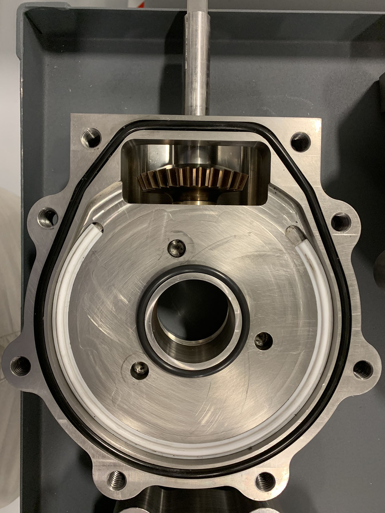
Clarke Valve engineers needed to devise a method for creating a tight seal on the upstream and downstream faces of the valve petals, while avoiding erosion, pitting, or tearing of any seals or gaskets during operation.
Solution
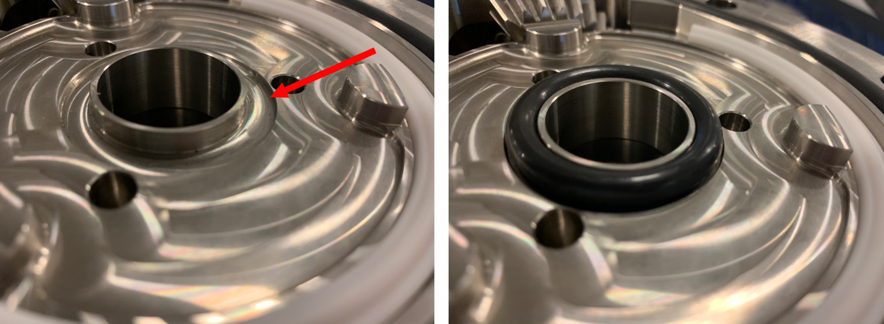
After extensive testing in Clarke Valve’s R&D facility, as well as with customers in the real world, our engineers identified a design solution that would protect the inner diameter O-ring seal surrounding the central aperture of the Dilating Disk™ Valve from particle impacts or fluid erosion, while still achieving a tight shutoff.
The axial face of each of the 3 petals is precisely machined to incorporate a curved arc-circle geometry. This approach benefits the Dilating Disk™ Valve in 2 ways:
- The arc-circle of the petal prevents a shearing motion across the face of the O-ring by avoiding any pinch points between 2 metal surfaces: the O-ring only comes into contact with any of the valve petals during the full closed position.
- The lip of the arc-circle on all 3 petals presses tightly against the O-ring in the fully closed position, compressing it against the edge of the valve port and the groove where the O-ring sits in the valve body and cover, effectively creating the second half of the O-ring groove.
Similar to the seals in the bonnet and valve body, Clarke Valve made a design decision to use standard, off-the-shelf sizes for the O-ring surrounding the valve port. While the arc-circle design helps the O-ring to survive high cycle fatigue and wear, the use of standard parts will ensure that any service or replacements of the soft goods in the Dilating Disk™ Valve is cost-effective, and immediately available in case of emergency, for the customer.
Results
By using the arc-circle design, Clarke Valve has extended the life of the interior diameter O-ring in each Dilating Disk™ Valve, while ensuring a tight seal when the 3 petals are in the fully closed position. Clarke Valve engineers have conducted 360,000 test cycles on a valve to successfully demonstrate the extended life of the O-ring seal, while maintaining the tight shutoff that results from this design.
Customers therefore benefit from longer periods between maintenance and greater overall uptime, while having total confidence in tight closure at ANSI Class IV, Class V, and even Class VI bubble-tight leakage ratings.