
The design of the valve in consideration of assembly, maintenance, and repair
The control valve landscape has been relatively unchanged for the last 50-plus years. Globe valve OEMs have rolled out different trim variations in an attempt to manage cavitation, noise, fugitive emissions, and other adverse operating conditions, but the general design principle is largely unchanged. The same applies for ball valves, butterfly valves, and other valve types that are ideally suited to shutoff functions, but which are sometimes pressed into service for process control.
The Dilating Disk™ Valve is a radical departure in form and function, from all of the above listed valve types; it will require unique classification in ISA and ASME valve standards.
Challenge
As we have described elsewhere, there are different types of barriers to the adoption of new technologies, and these must be addressed by product design and other strategies.
The Clarke Valve mission is “to continue to innovate and develop valves that customers, technical personnel, and engineers love to use,” which requires us to make the Dilating Disk™ Valve readily understandable not only to buyers, but to the operators and maintenance teams who will be responsible for installing and servicing the Dilating Disk™ Valve over its lifetime.
Solution
From the initial concept of the Dilating Disk™ Valve through to the ongoing R&D and design iterations, Clarke Valve’s engineering team has designed the valve for ease of assembly, maintenance, and repair. Every Dilating Disk™ Valve is sized and manufactured for zero modification installation with existing piping schedules and face-to-face dimensions. And, little or no additional training is required for operators or technicians to maintain a Dilating Disk™ Valve, once installed. Every valve comes with a bill of materials and a simple diagram describing assembly and maintenance procedures.
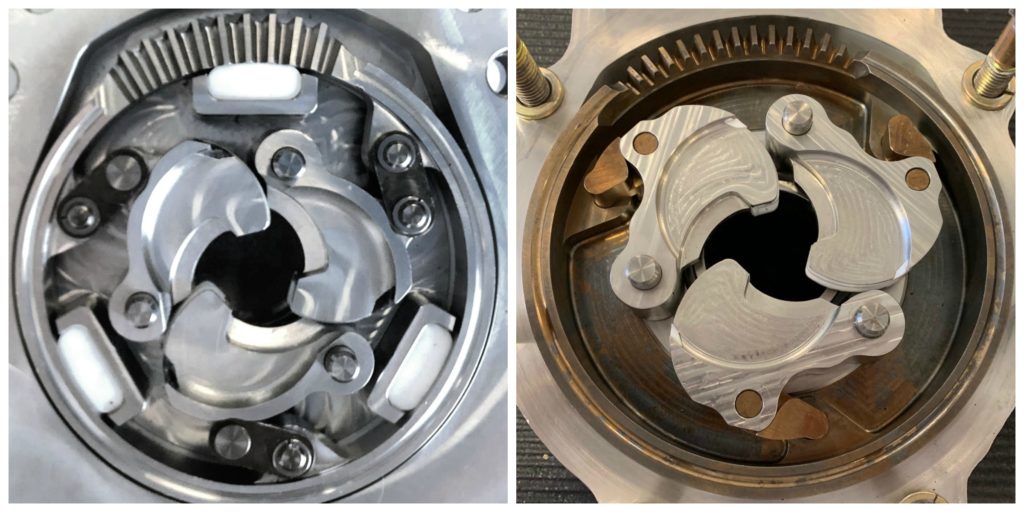
We achieved our goal of simplified assembly of the Dilating Disk™ Valve with the ingenious design of the ring gear, integral arms, and valve petals. The hub design of the ring gear dictates that it must go on the bottom, followed by the arms, and then the petals. Each of the arms is designed to ensure that it can only go into the ring gear one way. Likewise, each petal can only fit onto the arm and the guide pins in the valve body in the proper orientation. This prevents untrained personnel from making a critical assembly error.
Figure 1: Although the internal mechanism of the Dilating Disk™ Valve represents a departure from existing control valve designs, the components fit together intuitively without any special training or tools required. As described above, the ring gear, integral arms, and valve petals are designed to only allow assembly in one manner, preventing improper alignment of the components during maintenance or inspection.
There are no special tools required to extract or install the petals or the arms. The entire valve assembly can be removed and replaced by hand, once the bolts on the valve body and bonnet have been removed. The insertion points for each element are machined to a sufficiently precise tolerance to prevent play or instability, but still allow for hand assembly with minimal pressure.
Over time, Clarke Valve has made modifications to the design of the arms and petals to make the Dilating Disk™ Valve even simpler to assemble and service. Previously, there were 22 pieces comprising the valve mechanism, including 6 control arms (2 for each petal), 6 pins and 6 retaining rings, 3 petals, and 1 ring gear. The evolution of our design and the replacement of the linkages with integral arms has effectively reduced the number of valve mechanism parts to 7, including 3 petals, 3 arms, and 1 ring gear.
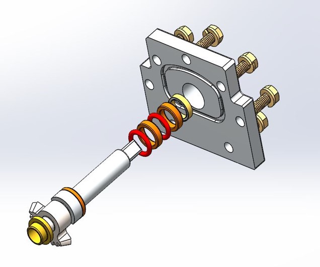
The Clarke Valve design philosophy also carries over to our selection of the soft goods that help to ensure tight shutoff in every valve. The O-rings for the valve body, bonnet and the stem seals are all commonly available, off the shelf sizes, and can be replaced by hand.
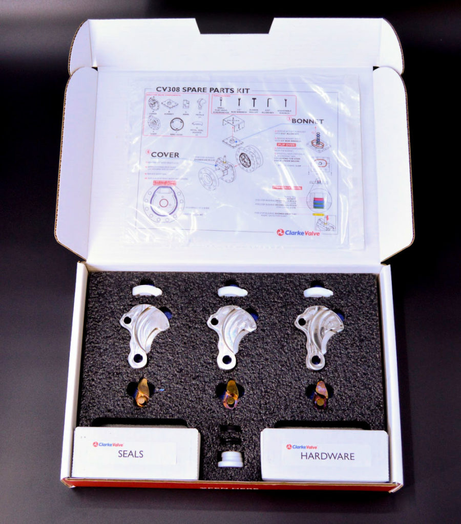
The seals that form the interlocking rib and seal combination between the 3 valve petals are provided as part of the Spares Kit for every valve. These seals come pre assembled into a new set of Petals which can be removed by hand. Again, no special tools are needed. New seals easily snap into place with hand pressure, once the old seal has been removed. Depending upon the valve application, these seals are either made of an elastomer or plastic composition.
The Dilating Disk™ Valve bonnet was also designed to reduce the need for ongoing maintenance, unlike the stem seals of globe valves, butterfly valves, and other common valve types. In its current configuration, the Dilating Disk™ Valve eliminates the live loading that occurs with the packing in these other valve types. The spring energized seals and bearings of the Dilating Disk™ Valve are held in the optimum sealing position by the bonnet itself. This eliminates the need to progressively tighten packing followers which inherently increases the torque required for stem movement/valve operation. In future design iterations, we may explore live loading. But, at present, the Dilating Disk™ Valve bonnet design outperforms existing stem sealing methods for other valve types.
Results
By focusing on an intuitive design for the valve mechanism, using off-the-shelf seals, and matching existing face-to-face dimensions for globe control valves, Clarke Valve has engineered the Dilating Disk™ Valve to be a superior plug-and-play replacement, that is easy for technicians to service and re-assemble.
The unique geometry of the Dilating Disk™ Valve and its significantly lower torque requirements means that it can replace a globe valve with comparable flow rate (CV), but with a 50% to 80% reduction in weight and overall footprint. This size and weight savings reduces the labor and time needed to install or replace a Dilating Disk™ Valve, conferring still further efficiency benefits to the industrial facility that chooses to deploy the Dilating Disk™ Valve.